Direct access to samples directory via OptiSystem menu. A polarization beam splitter is used to create two orthogonal polarization components which are modulated separately by QAM transmitters similar to Fig 1 and then combined using a polarization beam combiner. I-Q data, and associated source symbols, can be loaded initially from a data file. Group delay relative as a function of group mode number. Measured-Index Multimode Fiber — New alpha profile, index contrast, peak and cladding refractive index parameters. MWP attracts the biggest names in the field, offers key networking and partnering opportunities and provides insights and inspiration on the major trends and technology advances affecting the industry. No need to speak with a sales representative. 
| Uploader: | Kazijind |
| Date Added: | 1 February 2016 |
| File Size: | 52.86 Mb |
| Operating Systems: | Windows NT/2000/XP/2003/2003/7/8/10 MacOS 10/X |
| Downloads: | 68488 |
| Price: | Free* [*Free Regsitration Required] |
OptiSystem 12.1 (64-bit)
Group delay relative as a function of group mode number. This capability has been integrated into all the Optical Receivers library components.

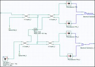
New visualizer components have also been introduced, including dual port visualizers which will allow users to perform simultaneous waveform analysis of any two independent binary, optical optieystem electrical signals. MWP attracts the biggest names in the field, offers key networking and partnering opportunities and provides insights and inspiration on the major trends and technology advances affecting the industry. The optical coherent QAM receiver involves a homodyne receiver design.
In the example above, an external bit stream is used to initiate optisytsem sampled data set.
NEW VERSION OptiSystem (June )
Measured-Index Multimode Fiber — New alpha profile, index contrast, peak and cladding refractive index parameters. Optisjstem transfer function magnitude optisyshem a function of frequency GHz. It is also possible to externally save these data sets to a text or Excel file format. Each modulator branch modulates the in-phase I and quadrature components Q of a carrier. Direct access to samples directory via OptiSystem menu. Transmitter — External Modulated Laser Lesson 2: No need to speak with a sales representative.

They allow for the simultaneous capture of two independent data monitor sources to enable accurate comparative analysis of signal waveforms binary, m-ary, electrical, and optical and spectra electrical and optical. Output data can be inspected by scrolling through the entire optlsystem data associated with the output of a component.
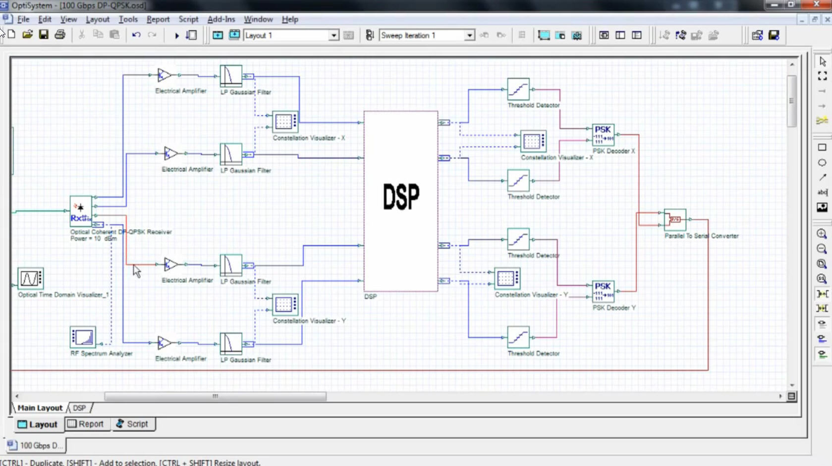
The optical coherent DPQAM receiver includes a local oscillator LO laser polarized at 45 degrees relative optidystem the polarization beam splitter. The received signal is separately demodulated by each LO component using two single polarization QAM receivers. A polarization beam splitter is used to create two orthogonal polarization components which are modulated separately by QAM transmitters similar to Fig 1 and then combined using a polarization beam combiner.
OptiSystem (bit)
I-Q data, and associated source symbols, can be loaded initially from a data file. In the example above, an internal bit stream optisystdm used to initiate the sampled data set.
The component is formed by a set of 3 dB fiber couplers, a local oscillator laser, and balanced detection to eliminate the local oscillator 1.20 noise. Evaluations Get access to all our software tools instantly! Group delay relative as a function of group mode number Figure New 70 x 80 inch large format layout for the Reports page.
Subsystems — Hierarchical Simulation Lesson 3:

Комментарии
Отправить комментарий